AmetekHaydonKerk AmetekAMS
Skip to content

Size 8 21mm

Size 8 Rotary Stepper Motor
The Size 8, 21 mm hybrid rotary motor is a compact, high performance stepper. At rated voltage, the Size 8 - 21000 series - single stack motors produce torque up to 11.8 mNm (1.7 oz-in). It excels but is not limited to medical equipment, semiconductor handling, valve control, X-Y tables, and handheld instruments.
  • Specifications +


    Part No. Rotary 21H40-V
    Wiring Units Bipolar
    Step Angle Degree 1.8°
    Winding Voltage VDC 2.5 5 7.5
    Current/Phase A rms 0.49 0.24 0.16
    Resistance/Phase ohms () 5.1 20.4 45.9
    Inductance/Phase mH 1.5 5.0 11.7
    Power Input Watts 2.45
    Rotor Inertia
    gcm2 1.4
    Insulation Class
    Class B (Class F available)
    Weight oz (g) 1.5 (43)
    Insulation resistance M() 20
    Standard motors are Class B rated for a maximum temperature of 130°C (155°C for Class F)

  • Dimensional Drawings +


    Size 8 Series 21000 Rotary Motor


    Size 8 Rotary
    Size 8 Rotary Motor

  • Performance Curves +


    Rotary Hybrid Size 8


    NOTE:  All chopper drive curves were created with a 5 volt motor and a 40 volt power supply.

    Ramping can increase the performance of a motor either by increasing the top speed or getting a heavier load accelerated up to speed faster.  Also, deceleration can be used to stop the motor without overshoot.

    With L/R drives peak force and speeds are reduced, using a unipolar drive will yield a further 30% force reduction.


  • Encoders +


    All Haydon hybrid linear actuators are available with a specifically designed encoder for applications that require feedback. The compact optical incremental encoder design is available with two channel quadrature TTL squarewave outputs. An optional index is also available as a 3rd channel. The size 8 encoder provides resolutions for applications that require 250 and 300 counts per revolution.  The size 11, 14 and 17 encoder provides resolutions for applications that require 200, 400 and 1,000 counts per revolution.  The size 23 and 34 encoder is offered in resolutions of 200, 400, 1,000 and 2,000 counts per revolution. Encoders are available for all motor configurations — captive, non-captive and external linear.

    Simplicity and low cost make the encoders ideal for both high and low volume motion control applications. The internal monolithic electronic module converts the real-time shaft angle, speed, and direction into TTL compatible outputs. The encoder module incorporates a lensed LED light source and monolithic photodetector array with signal shaping electronics to product the two channel bounceless TTL outputs.

    Electrical Specifications

      Minimum 
    Typical 
    Maximum 
    Units 
    Input Voltage
    4.5 5.0 5.5 VDC
    Output Signals
    4.5 5.0 5.5 VDC
    • 2 channel quadrature TTL squarewave outputs
    • Channel B leads A for a clockwise rotation of the rotor viewed from the encoder cover
    • Tracks at speeds of 0 to 100,000 cycles/sec.
    • Optional index available as a 34d channel (one pulse per revolution).


    Single Ended Encoder Pinout Size 8

    Connector Pin # 
    Description 
     1 +5 VDC Power
    2 Channel A
    3 Ground
    4 Channel B


    Operating Temperature

    Minimum
    Maximum
    -10°C (14°F)  
    85°C (185°F) 


    Mechanical Specifications

      Maximum
    Acceleration 250,000 rad/sec2
    Vibration (5 Hz to 2 kHz)
    20g


    Resolution
    4 standard Cycles Per Revolution (CPR) or Pulses Per Revolution (PPR)

    CPR 
    250 300
    PPR
    1000 
    1200 

    Others are available

    Encoder Dimensional Drawing
    Dimensions = (mm) inches

    21mm 21000 Series Size 8

    Size 8 Linear Actuator Encoder
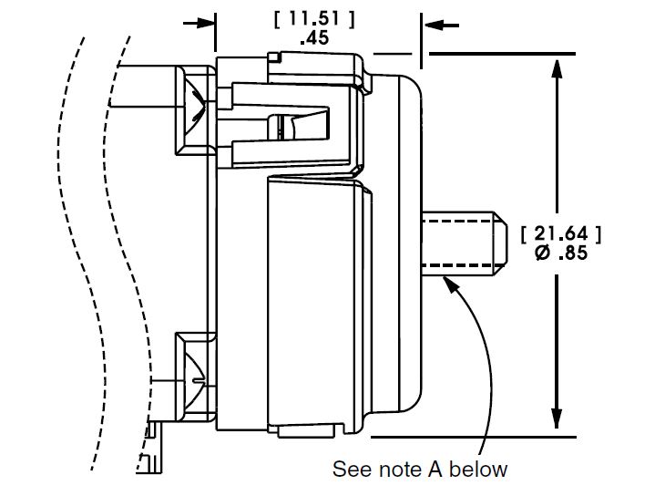
    Note A: Lead screw extends beyond encoder on specific captive and non-captive motors. External linear shaft extension is available upon request.

    Please note: Metric numbers are for reference only.

  • Integrated Connectors +


    Offered alone or with a harness assembly, this connector is RoHS compliant and features a positive latch in order for high connection integrity. The connector is rated up to 2 amps and the mating connector will handle a range of wire gauges from 24 to 28. Ideal for those that want to plug in directly to pre-existing harnesses.

    Motor Connector:
    JST part # S04B-ZESK-2D

    Mating Connector:
    JST part # ZER-04V 
    Haydon Kerk Part # 56-2369-1 (12 in. Leads)

    Wire to Board Connector:
    JST part # SZE-002T-P0.3
       
  • Wiring Diagram and Stepping Sequence +


    Bipolar Wiring Diagram

    Stepping Sequence- Hybrid Linear Actuator

    Bipolar Q2-Q3 Q1-Q4 Q6-Q7 Q5-Q8
    Step . . . .
    1 ON OFF ON OFF
    2 OFF ON ON OFF
    3 OFF ON OFF ON
    4 ON OFF OFF ON
    1 ON OFF ON OFF
  • Part Number Guide +


    21

    H

    4

    0

    -

    7.5

    -

    900

    Series Number
    Designation

    Style

    Coils

    Code ID
    Resolution Travel/Step


    Voltage


    Suffix

    21=21000 (Series numbers
    represent approximate width of motor body)

    H=1.8°Step Angle, Single Stack

    4=Bipolar
    (4 wire)


    0=Rotary Motor


    2.5=2.5 VDC
    05=5 VDC
    7.5=7.5VDC
    Custom V available


    Example:
    900=Catalog Motor
    XXX=Proprietary suffix assigned to a specific customer application. The identifier can apply to either a standard or custom part.


    NOTE: Dashes must be included in Part Number (–) as shown above. For assistance call our Engineering Team at 203 756 7441.